

Products overview:
ZW - LGK seriesOrifice flowmeterIs the standard orifice differential pressure transmitter with multiple parameters (or differential pressure transmitter, temperature transmitter and pressure transmitter) form a complete set of high contrast range pressure flow device, capable of measuring gas, steam, liquid and flow, widely used in petroleum, chemical industry, metallurgy, electricity, heating, water supply in areas such as process control and measurement.Throttling device, also known as differential pressure flowmeter, consists of a test piece (throttle) and the second device (differential pressure transmitter and flow display) is widely applied in gas.Steam and liquid flow measurement.It has a simple structure, convenient maintenance, stable performance.
Second, the working principle:
ZW - LGK seriesOrifice meter is to be full of pipeline fluid, when they flow through the pipe orifice flow, flow velocity in the flow orifice throttling of the formation of local contraction, accelerated to flow, static pressure is reduced, so the standard orifice plate before and after the pressure drop is produced or differential pressure, the greater the flow medium traffic, the flow before and after the orifice of the greater the pressure difference, so can be measured by a pressure difference to measure the size of the fluid flow.This kind of measurement method based on flow continuity equation (conservation of mass) and the Bernoulli equation (energy conservation) based on the principle of.Under the condition of known related parameters, according to the principle of flow continuity and Bernoulli's equation can be deduced the relationship between the pressure and flow rate and flow rate are obtained.The basic formula is as follows:
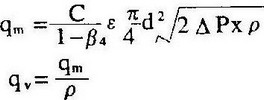
C - outflow coefficient of dimensionless
D - working conditions or throat diameter of throttle orifice
Upstream pipe diameter D - working conditions
Qm - mass flow Kg/s
Qv - volume flow m3 / s
- diameter ratio d/d dimensionless
The density of fluid Kg/m3
Dimensionless expansiveness coefficient
Applications:
ZW - LGK seriesOrifice meter is the standard orifice differential pressure transmitter with multiple parameters (or differential pressure transmitter, temperature transmitter and pressure transmitter) form a complete set of high contrast range pressure flow device, can measure the rate of flow of gas, steam, liquid and gas, widely used in petroleum, chemical industry, metallurgy, electricity, heating, water supply in areas such as process control and measurement.
Four, the main features:
1, the throttle device structure easy to copy, simple, firm, stable and reliable performance, long service life, low price.
2, orifice calculation adopt international standards and processing.
All three, wide application range, single phase flow are measured, partially miscible flow can also be applied.
4, standard throttle device without real flow calibration, putting-in-service proactively.
5, a body orifice plate installation is more simple, do not need to bring pressure pipe, can be directly answering the differential pressure transmitter and pressure transmitter.
Five, the technical parameters:
CAL: DN25 ~ DN1000 (mm);
Accuracy: + / - 1% FS.
Range than: standard 1:13, expanding 1:30;
Working pressure: 42.0 MPa or less;
Medium temperature: - 40 c ~ 450 c;
Medium viscosity: 30 or less cp (crude oil);
Beta: 0.2 ~ 0.8;
Connection mode: flange or clamp type;
The flange standard:
DN≤600mm, PN2.0~PN26,HG20616;PN32,HG20618;
DN>600mm,PN2.0~PN15,HG20623;
Can also be made according to standard provided by the user flange;
Material: subject, orifice plate, pressure pipe, three valve group: stainless steel;Straight pipe and the connecting flange: carbon steel or stainless steel;
Installation method: horizontal or vertical;
Smart differential pressure transmitter: output: 4 ~ 20 ma. DC or digital signal;Power: 24 v DC;
Explosion-proof grade: d Ⅱ CT5.6, ia Ⅱ CT4-6;Protection grade: IP67;
Header: blind table and digital display table two.
Six, the classification of the structural features:
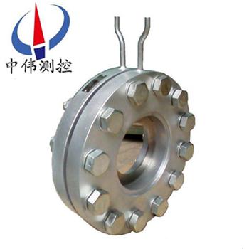
1, annulus pressure standard orifice:
The standard orifice plate.Due to implement the annulus pressure, improves the measuring accuracy, shortens the installation time required zui small straight section length and can be widely used in each department.
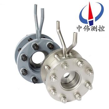
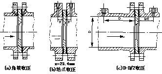
2, Angle joint single borehole pressure standard orifice:
The standard orifice plate.When more than 400 mm in diameter, with this form.Take pressure method for flange single borehole pressure, circular equalizing ring or square take pressure equalizing ring.Orifice form can provide with handle holes or non-standard segmental orifice plate, etc.
3, flange pressure standard orifice:
The standard orifice plate.Upstream or downstream regardless of pipe diameter size, its take pressure hole center, located on both sides of the orifice plate face one (25.5 mm), each of the various refining system widely used this form.
4, diameter pressure standard orifice:
The standard orifice plate.Take pressure method for pipeline pressure.Take pressure upstream hole center is located in the front of the orifice pipe diameter.Take pressure hole center is located in the downstream distance orifice and a half after the end of pipe diameter.
5, small-bore orifice:
The standard orifice plate.Used to measure fluid within 10 mm to 50 mm diameter measurement.
6, double orifice:
Is the distance from each other in a certain installed on the straight pipe of the two pieces of standard orifice plate.According to the flow direction of the beam, the hole in front of the said is complementary orifice plate, the back of the orifice said orifice.Auxiliary orifice cross-section than m1 is greater than the main section of orifice than m.Two pieces of orifice plate makes the walls of a similar liquid nozzle.It is used for low Reynolds number or high viscosity fluid flow measurement.
7, segmental orifice:
Belong to non standard orifice, be applicable to the dirt, or have a bubble analysis, or contains solid particles in the measurement of fluid flow and its measurement precision is low.
8, conical inlet orifice:
The standard orifice plate.Circular cone with the center line of the Angle is 45 °, the conical inlet orifice can suitable for occasions with low Reynolds number, but shall not be less than 25 mm pipe size.
Seven, maintenance, installation of pipeline conditions:
1, the straight pipe before and after the throttle articles must be straight, bend shall not be visible to the naked eye.
2, install throttle with straight pipe should be smooth, if not smooth, flow coefficient should be multiplied by the roughness correction sparse.
3, in order to ensure the flow of the fluid in the formation of throttling a 1 d before the full development of the turbulent velocity distribution, and makes the distribution into uniform axisymmetric shape, so
1) straight pipe must be round and throttling range 2 d before, its roundness, its very strict and have certain roundness index.Specific measures:
OD before throttling (A) A, D / 2 D, 2 d4 on the vertical pipe section, by A large distance at least equal to the Angle of the measured four pipe diameter single measurements, the average D.Any diameter single measured value and the difference between the average shall not exceed + / - 0.3%
(B) after the throttle piece, the OD and 2 D location using the above method obtained eight diameter single measurement value of arbitrary single measurement values compared with D, the zui big deviation shall not be more than + / - 2%
2) throttling requires a enough long straight pipe before and after the long enough straight pipe and throttle and diameter on the local resistance of a form before than beta.
3) throttling pieces of upstream side * resistance and the resistance between the straight pipe length according to the form of a second resistance and beta = 0.7 (no matter what is the actual beta) select listed number 1/2
4) throttling upstream side for open space or a diameter of 2 d large container, or open space or a large container with throttling a long straight tube shall not be less than 30 d (d).If throttling and open space or there are other local resistance between large container, except in throttling and local resistance parts has set rules annexed zui between small straight long 1, from the open space to the throttling parts between the straight pipe section chief, also should not be less than 30 d (d).
Eight, notable matters of installation:
1, can be horizontal, vertical or inclined installation, should guarantee the tube filled with liquid.
2, the throttle device before and after the straight pipe should be straight, bend without visible to the naked eye, at the same time, should be "round", inner surface should be clean, without potholes and sediment;
3 and the request of straight section length and throttling device installation should be in conformity with the relevant provisions of the GB/T26224-93.
4, lead pressure pipeline installation should comply with the standards stipulated by the regulations.
Nine, scope of application and characteristics:
Throttling a name | Apply pipe (DN mm) | Apply to diameter ratioB(d/D) | Application characteristics | Uncertainty of outflow coefficientEc% | Design criteria | |
Angle of access standard orifice plate | Ring chamber type | 50-500 50-500 | 0.2-0.75 0.2-0.75 | Apply to clean mediumGDUnder the condition of structure is suitable for high temperature and high pressure flow rate measurement | 0.6-0.75% | ISO5167 GB/T2624-93 |
The clamping ring type | 50-500 | 0.2-0.75 | Easy to remove dirt, and can be used to clean fluid flow measurement | |||
Oblique hole type | 450-1000(3000) | 0.2-0.75 | ||||
Flange pressure standard orifice plate | 50-1000 | 0.2-0.75 | Easy to remove dirt, and are suitable for all kinds of media | 0.6-0.75% | ISO5167 GB/T2624-93 | |
Span with standard orifice plate | 50-1000 | 0.2-0.75 | ||||
Angle access standard pressure nozzle (ISA1932Nozzle) | 50-500 | 0.3-0.8 | Small pressure loss, long life, especially suitable for steam flow measurement | 0.8-1.2% | ISO5167 GB/T2624-93 | |
The length to diameter nozzle | 50-630 | 0.2-0.8 | Small pressure loss of long service life,LGPType of length to diameter nozzle components for high parameters of water and steam flow measurement | 2.0% | ISO5167 GB/T2624-93 | |
Classic venturi tube | Mechanical processing type | 100-800 | 0.2-0.8 | The pressure loss is small, straight pipe required less than orifice, nozzle | 1.0% | ISO5167 GB/T2624-93 |
Soldering iron plate type | 200-1200(2000) | 0.4-0.7 | 1.5% | |||
Venturi nozzle | 65-500 | 0.316-0.77 | Same as above | 1.2-1.75% | ISO5167 GB/T2624-93 | |
A quarterRound hole plate | 25-150 | 0.245-0.6 | Suitable for low Reynolds number | 2.0-2.5% | DIN BS | |
Conical inlet orifice | 25-250 | 0.1-0.316 | Same as above | 2.0% | BS | |
Segmental orifice | 50-1500 | 0.32-0.8 | Apply to the smudges, there are air bubbles or containing solid particles flow measurement. | 1.5% | DIN | |
The eccentric orifice plate | 100-1000 | 0.46-0.84 | 1-2% | ASME | ||
Small hole plate | 12.5-40 | 0.2-0.75 | Applicable to small pipe flow measurement | 0.75% | ASME | |
Lens type orifice | 12.5-150 | 0.2-0.75 | Suitable for high pressure temperature small pipe flow measurement | 0.6-0.75% | ISO5167ASME | |
Ten, classification model parameter table:
The name of the | model | Take pressure way | Nominal pipe diameter (mm) | Nominal pressure (MPa) | Execution standard (structure) |
The standard orifice plate | LGK | Pressure Angle joint (annulus) | 50~400 | Less than10 | GB2624 K07 |
LGB-Z | Pressure Angle joint (drilling) | 400~2000 | Less than1.6 | ||
LGK | Ring chamber (8 slot) | 50~400 | Less than32 | The flow measurement manual | |
LGK | Ring room (no flange welded) | 50~275 | Less than28.22 | The flow measurement manual | |
LGB-F | The flange to take pressure | 50~800 | Less than2.5 | GB2624 K06 | |
LGB-F | The flange to take pressure | 50~400 | 4.0~40 | GB2624 K06 | |
LGB-J | Diameter of pressure | 50~760 | Less than10 | GB2624 | |
Standard nozzle | LGP | Pressure Angle joint (annulus) | 50~400 | Less than10 | GB2624 The flow measurement manual |
LGP-Z | Pressure Angle joint (drilling) | 400~500 | Less than1.6 | ||
LGP | Ring chamber (8 slot) | 50~300 | Less than32 | The flow measurement manual | |
LGP | Ring room (high pressure lens pad) | 15~150 | Less than32 | ||
LGP | Ring room (no flange welded) | 175~350 | Less than17.36 | DG 0702~0710 | |
The length to diameter nozzle | LGC-J | Diameter of pressure | 50~630 | Less than16 | GB2624 |
A quarterRound hole plate | LGH | Take pressure Angle joint | 50~260 | Less than10 | GB2624 The flow measurement manual |
LGH-F | The flange to take pressure | 50~200 | Less than6.4 | ||
Venturi nozzle | LGL | Take pressure Angle joint | 65~500 | Less than2.5 | |
Venturi tube | LGW | Take special pressure | 50~1200 | Less than2.5 | |
Double venturi tube | LGW-S | Take special pressure | Less than1000 | Less than0.6 | |
Small diameter orifice | LGX | Take pressure Angle joint | 12~40 | Less than6.4 | K07(LanHua) |
LGX-F | The flange to take pressure | 12~40 | Less than6.4 | The enterprise standard | |
High pressure lens gasket | LGT | Take pressure Angle joint | 50~150 | Less than32 | The flow measurement manual |
Segmental orifice | LGQ | Pressure Angle joint (annulus) | 100~400 | Less than1.6 | |
LGQ-Z | Pressure Angle joint (drilling) | 400~1000 | Less than1.6 | ||
LGQ-F | The flange to take pressure | 100~350 | Less than6.4 | ||
Double orifice | LGS | Take pressure Angle joint | 100~400 | Less than6.4 | |
The eccentric orifice plate | LGN | Take pressure Angle joint | 100~1000 | Less than6.4 | |
Current limit orifice | LG-XL | 10~300 | Less than6.4 | The enterprise standard | |
Conical inlet orifice | LGR | Take pressure Angle joint | 25~1000 | Less than10 | GB2624 |
The wing wind device | LJY | Take special pressure | Less than1000 | Less than0.6 | The enterprise standard |
Eleven,Selection of code:
model | said Ming | ||||||||
ZW-LG | The throttle device (wei measurement and control) | ||||||||
Code name | According to the structure characteristics of the two basic categories | ||||||||
K | The standard orifice plate | ||||||||
P | Standard nozzle | ||||||||
Code name | Nominal pressure (105Pa) | ||||||||
2.5 | 2.5 | ||||||||
10 | 10 | ||||||||
16 | 16 | ||||||||
25 | 25 | ||||||||
64 | 64 | ||||||||
100 | 100 | ||||||||
200 | 200 | ||||||||
Code name | CAL(mm) | ||||||||
15~1200 | 15~1200mm | ||||||||
Code name | According to its structure form of segmentation | ||||||||
H | The standard orifice plate(Ring chamber) | ||||||||
Y | The standard orifice plate(The flange) | ||||||||
K | The standard orifice plate(drilling) | ||||||||
I | ISA 1932The nozzle | ||||||||
L | The length to diameter nozzle | ||||||||
W | Venturi nozzle | ||||||||
G | Classic venturi tube | ||||||||
S | Double orifice | ||||||||
Q | Segmental orifice | ||||||||
Z | Conical inlet orifice | ||||||||
R | A quarterRound hole plate | ||||||||
P | The eccentric orifice plate | ||||||||
N | As a whole(Hidden within)Orifice plate | ||||||||
X | Wedge orifice | ||||||||
T | Out of place in the above special throttling device | ||||||||
Code name | medium | ||||||||
1 | liquid | ||||||||
2 | gas | ||||||||
3 | steam | ||||||||
4 | High temperature liquid | ||||||||
Code name | Compensation in the form of | ||||||||
N | Without pressure and temperature compensation | ||||||||
P | With pressure compensation output | ||||||||
T | With temperature compensation output | ||||||||
Q | With compensation output pressure and temperature | ||||||||
Code name | Differential pressure transmitter range scope | ||||||||
0 | Micro differential pressure range | ||||||||
1 | Low differential pressure range | ||||||||
2 | The differential pressure range | ||||||||
3 | Elevation difference pressure range | ||||||||
Code name | Whether or not to bring a live show | ||||||||
W | The throttle device sensors | ||||||||
X | Intelligent throttling device | ||||||||
13 order, design notes:
When you place an order, please provide the following conditions in order to help the correct choice of the specifications of the flowmeter and coefficient.
1, pipe size: diameter x wall thickness (mm);
2, measuring medium name: medium density (kg/m3);
3, set the flow range: meter range of upper limit and lower limit (kg/h or m3 / h);
5, work pressure (Mpa);
6, work temperature: (° C);
7, such as wei in my company, please provide together: intelligent flow totalizer.especially pressure range, or pressure transmitter type, range;Temperature range, or models, range temperature transmitter.
After-sales service commitment:
1, from the date of signing of the contract, I in the way provided for products of the company offers free maintenance and maintenance service, commitment to lifelong maintenance service;
2, jiangsu wei measurement and control instrument co., LTD. Sales manager will be in regular contact with customers, understand the usage of products, and solve the problems of the customers to use in the process of produce, free of charge to provide technical support;
3 the man-made damage is found, the warranty period, our company is responsible for the maintenance, and the resulting maintenance fee;
4, product quality problems or are not satisfied with product, the user can choose unconditional return, wei tt&c don't charge any fees, appear quality problem, bear the freight back and forth.
